sheet metal drawing standards
ANSI the American National Standards Institute has accredited SMACNA as a standards-setting organization. I see including a table with one row as drafting clutter.
Freelance Sheet Metal Design Services For Companies Cad Crowd
The minimum recommended sheet metal flange bend length avoid cracks in the bending area.
. Sheet metal is one of the shapes and forms metal can be bought in. Lower-left corner of the drawing sheet touching the left and bottom border lines 3. I am not aware of standards for them separate from any other kind of fabrication drawing.
The Sheet Metal Parameters dialog box is displayed. I do not put a BOM table on the drawing if the product has only one component. Form height to thickness ratio To determine the minimum form height for sheet metal use the following formula.
3 blade mechanical broadheads. We identified it from obedient source. Drawing upon the considerable experience of its own CADD Task Force.
Standard in which case AS SHOWN should be noted on the drawing. It shall be equal to three times of sheet thickness plus bend radius. For low carbon steel the minimum radius can be ½ the sheet thickness or 080 mm 003 whichever is greater.
Millimetres Mils Gauge. ANSI Y1471-1971 Gear Drawing Standards Part 1. BRASS Low carbon steel contains 005-032 carbon compared to medium high and ultra-high carbon steel.
Sheet metal is any metal that has a thickness in between 056 millimetres. Click the Sheet Metal Parameters icon. Our deeper draw capacity offers you completely customized options.
I assume they are pretty good. Ad We create customized parts in the exact size shape and material you need. 215 On detail drawings with 3 or more hole sizes holes shall be tabulated using the label shown.
Local depression and pressure line. A description is not available for this item. Architectural sheet metal is the original green roofing solution Detailed commentary and drawings Sheet Metal Roof Test UL Standard 580Factory Mutual Arioner Download Failed Preparing architectural drawings layouts landscaping and architectural floor plan are the key areas of architectural CAD drafting services United States.
9981870 - Drawing Compounds Water Based for Sheet Metal. 216 For slots callouts for CENT TYP and RADIUS or R are assumed. Vast number of techniques and materials.
Sheet metal shops can bend to tolerances of 015 or 04mm. This includes equipment finishing assembly fastening and the availability of standard dies. This gives brass sheet a wider range of performance depending on end use of the designed part.
Order and track sheet metal components online through Komaspecs on-demand sheet metal fabrication platform. These varying techniques allow make it possible to create relatively complex parts by cutting flat sheets bending parts into place and adding holes slots and notches cut in all the right places. D 25T R see below The height can be less but it required secondary operations and is far more costly.
Defining the Sheet Metal Parameters This task shows you how to configure the sheet metal parameters. In this article alone fourteen types of sheet metal fabrication are mentioned. Minimum Sheet Metal Flange Bend Length 3 x Sheet Thickness Bend Radius.
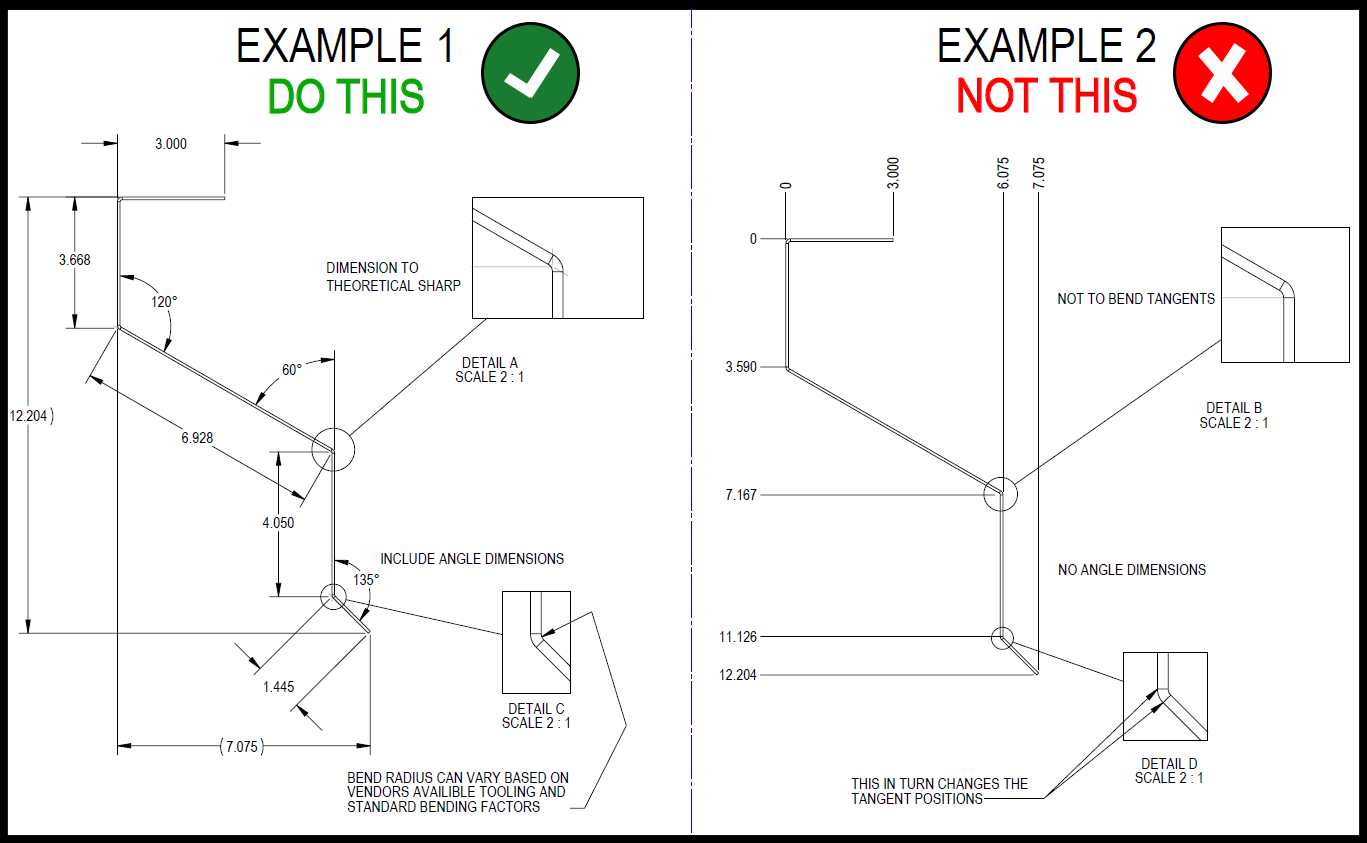
I do lots of sheet metal drawings. These factors all play a role in why most manufacturers dont want you to dimension parts in the flat pattern. January 1 2020 - GMNA.
Enter 5mm in the Default Bend Radius field. Because multiple components are in the product a bill of materials is needed. It reviews general dimension standards as well as requirements for.
Your tolerances to and from bends should reflect this. This video demonstrates how to properly dimension a sheet metal layout technical drawing. Its submitted by admin in the best field.
Although notes on each drawing will differ the first note on all sheet metal drawings They are going to consider the fact that. The radius of an inside bend should be at least equivalent to the materials thickness to avoid fractures or distortion. 2 blade mechanical broadheads.
Select the Bend Extremities tab. Foils sheets and plates are pretty much the same with the only difference being in thickness. We say yes this kind of Sheet Metal Drawing Standards graphic could possibly be the most trending subject later than we portion it in google benefit or facebook.
214 All tapped holes are assumed to have coarse threads unless otherwise specified. Offsets should follow the same sheet metal design guidelines as other bends. Here are a number of highest rated Sheet Metal Drawing Standards pictures upon internet.
SCS articulates the CAD standards that will enable SMACNA members and the rest of the AEC community to apply CAD effectively to mechanical fire protection and plumbing design and construction. Above the title block touching the right border line and the title block 4. Lower-left corner of the drawing sheet touching the left and bottom border lines 3.
This specification details the requirements for water based drawing compounds that provide additional lubricity to aid in metal forming operations and must be compatible with current production. Sheet Metal Drawing Standards - 17 images - bending basics strategies for forming offsets steel detailing drawings download free 3d model by hadeer cad crowd office fire resistant decorative wall panels smacna gutters saf southern aluminum finishing co inc saf. We typically use C2680 for sheet metal forming.
Upper-left corner of the drawing sheet touching the top and left border lines 2. The variation becomes larger as the bend angle increases and the part will no longer pass inspection. However once you expand over all four bends that number increases to a difference of 130 on the overall flat length of the part.
I have never checked the accuracy of the punching or laser cutting or whatever. SMACNA standards and manuals address all facets of the sheet metal and HVAC industry including duct construction and installation indoor air quality energy recovery roofing and architectural sheet metal welding and commissioning. Depending on the quantity of zinc in the alloy.
Enter 1mm in the Thickness field. Confirm the drawing formats with your fabricator to be sure they have no difficulty reading or interpreting your design. There are other measurement units used to categorise metals by thickness though.
This makes low carbon steel a more cost-eective choice. In the example shown in Figure 1 we have captive fasteners installed in a sheet metal part. To the left of the title block touching the bottom border line and the title block.

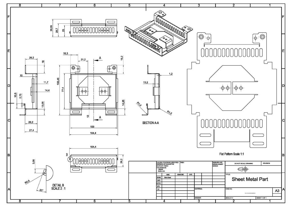
Sheet Metal Dimensional Drawing Example Vista Industrial Products Inc
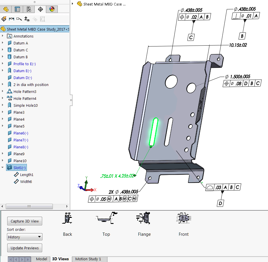
How To Define The Mbd Data Of Sheet Metal Parts Engineers Rule
Freelance Sheet Metal Design Services For Companies Cad Crowd
Dimensioning For Ease Of Manufacturing

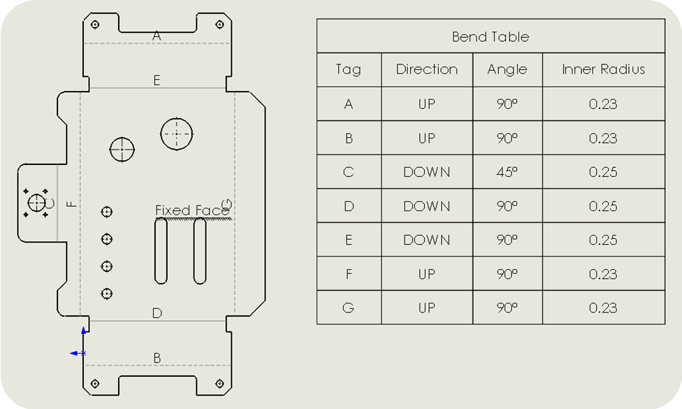
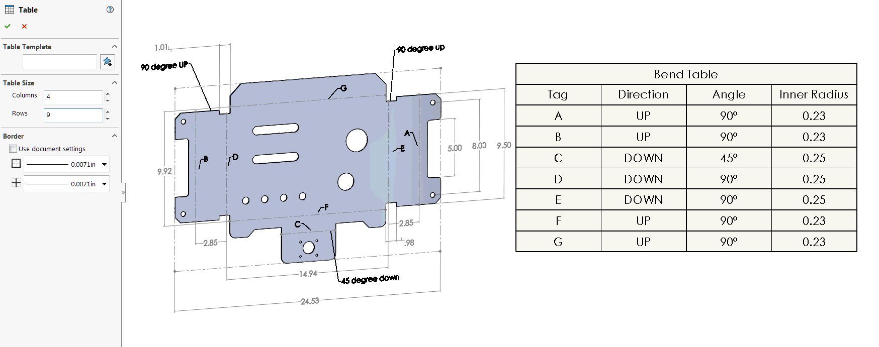
Solidworks Sheet Metal Drawing Tutorial Bend Line Flat Pattern Unfolded Bend Table Punch Table Youtube

Sheet Metal Tolerance Standards
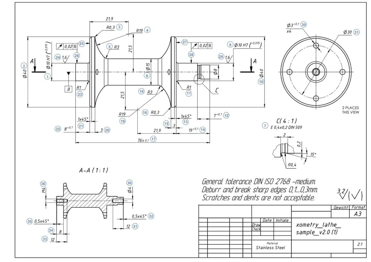
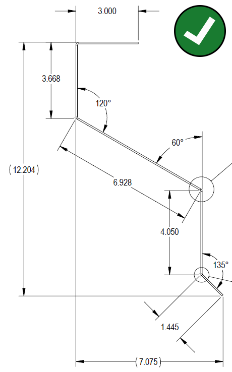
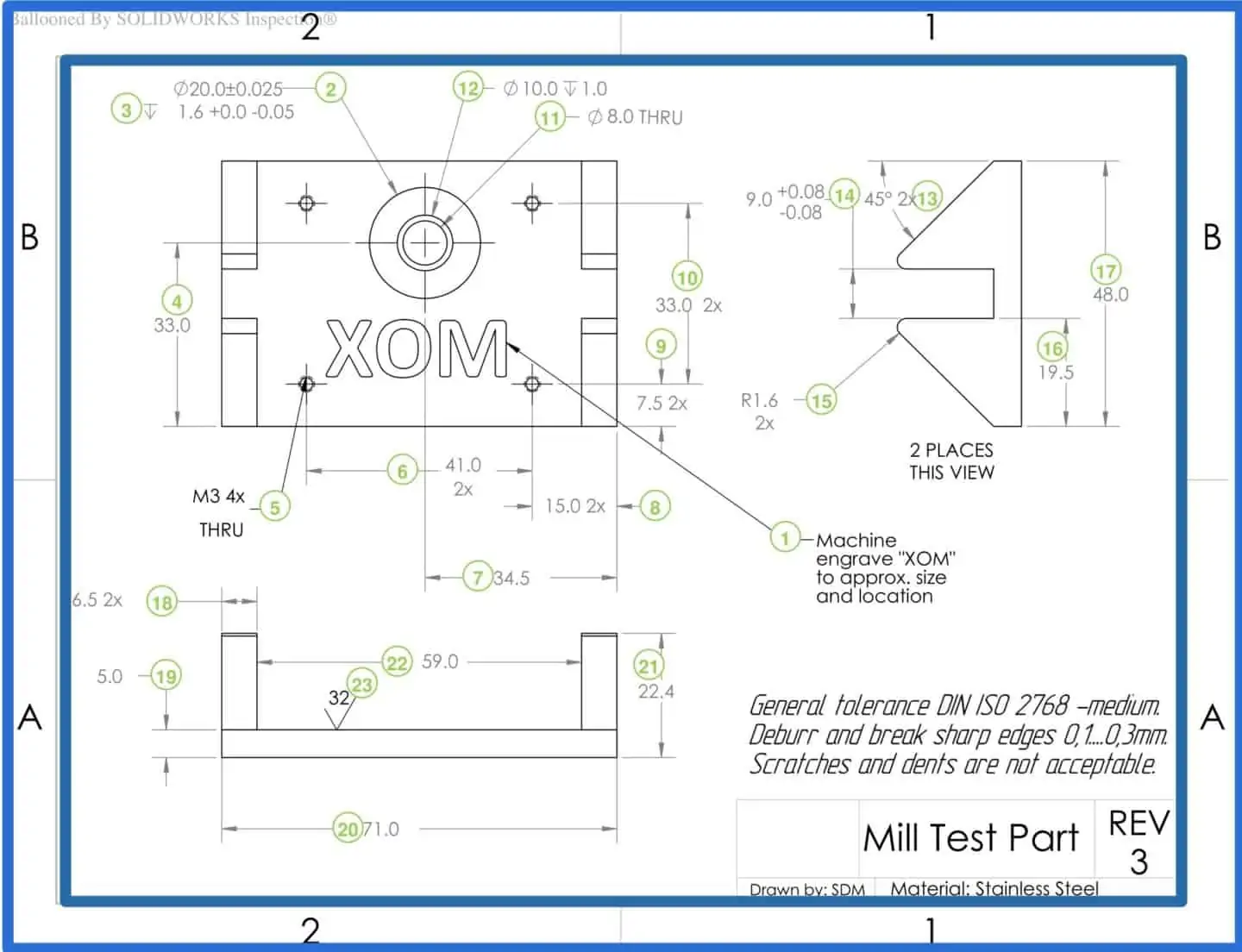
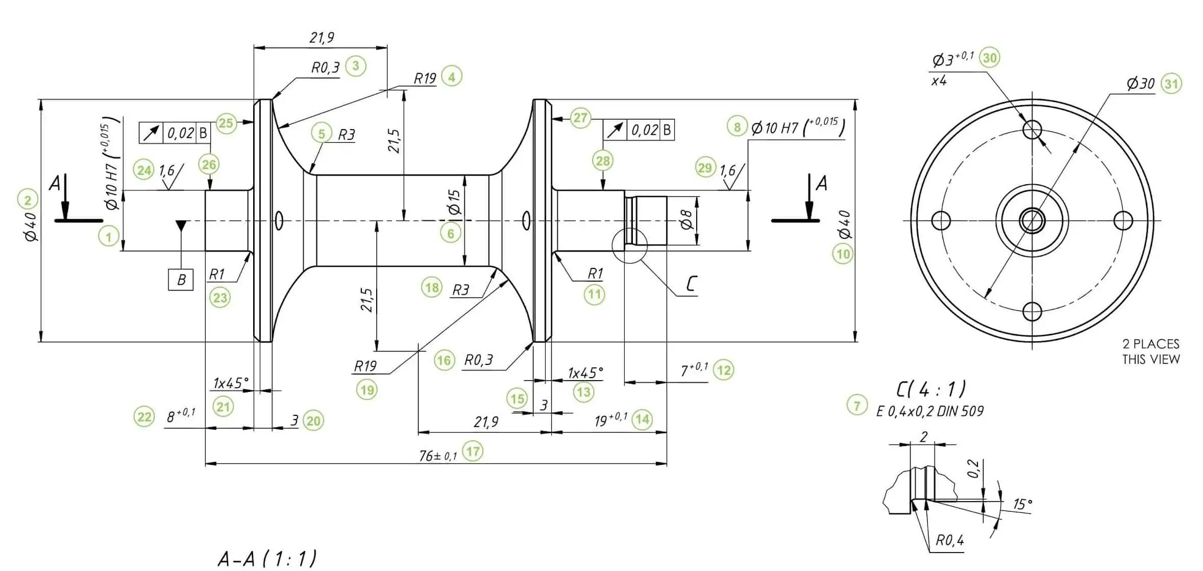
How To Prepare A Perfect Technical Drawing Xometry Europe

Sheet Metal Dimensional Drawing Example Vista Industrial Products Inc
Dimensioning For Ease Of Manufacturing
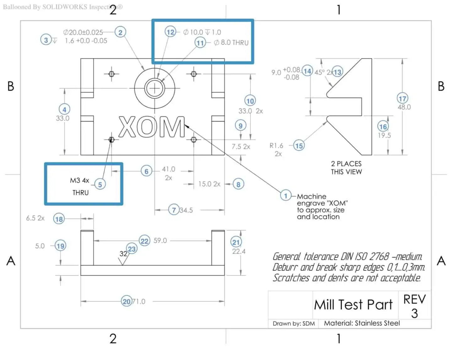
How To Prepare A Perfect Technical Drawing Xometry Europe
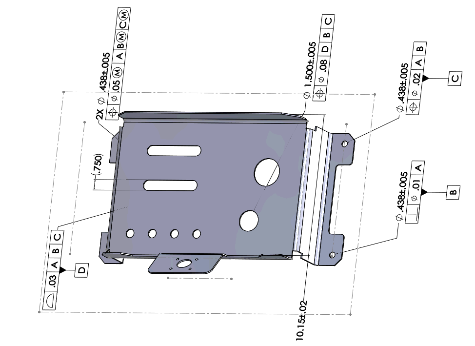
How To Define The Mbd Data Of Sheet Metal Parts Engineers Rule
How To Define The Mbd Data Of Sheet Metal Parts Engineers Rule

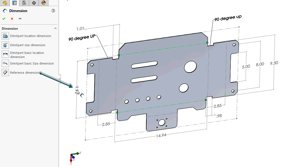
New To Sheet Metal Looking For Feedback About Dimensioning Autodesk Community Inventor
How To Prepare A Perfect Technical Drawing Xometry Europe

New To Sheet Metal Looking For Feedback About Dimensioning Autodesk Community Inventor
How To Define The Mbd Data Of Sheet Metal Parts Engineers Rule

Using Solidworks Sheet Metal Functionality Create A B Size Drawing Sheet Metal Drawing Technical Drawing Mechanical Engineering Design
How To Prepare A Perfect Technical Drawing Xometry Europe
How To Define The Mbd Data Of Sheet Metal Parts Engineers Rule